Vector layers, introduced in Toolbag 5, provide a non-destructive, resolution-independent way to add surface details using editable vector shapes. Vectors can be drawn, projected, and modified directly within a Texture Project, allowing precise control over lines, solid shapes, and modular strip-based details. This is useful for creating panel lines, decals, trims, and path-based details without adding geometry or baking textures.
3D Vector #
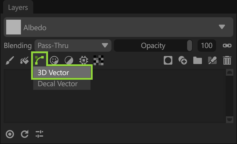
Add a 3D Vector layer from the Layers window toolbar.
All vector layers use a consistent set of settings sections for controlling vector behavior, shape generation, placement, and output.
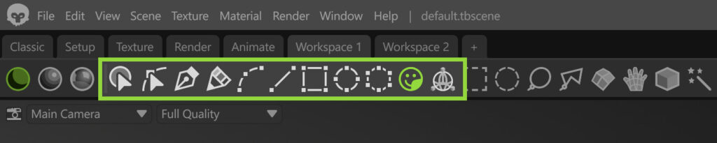
Toolbar #
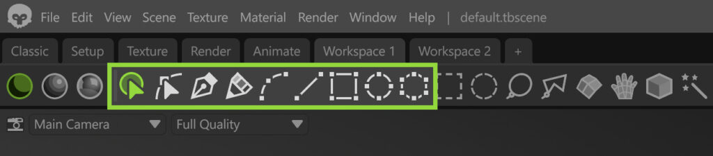
The toolbar provides quick access to tools for creating, selecting, and editing vector shapes within a Vector layer.
| Setting | Description |
|---|---|
| Select Shape | Select and edit a shape. Use this tool to select an entire vector shape. |
| Select Point | Select and edit points. Use this tool to select individual or multiple points. |
| Pen | Creates vector shapes by placing points to form paths and shapes. |
| Sketch | Draws vector shapes by sketching freehand paths directly on the surface. |
| Curve | Creates smooth vector paths by placing and adjusting curved segments. |
| Line | Creates straight vector paths by placing line segments. |
| Rectangle | Creates rectangular vector shapes. |
| Ellipse | Creates elliptical or circular vector shapes. |
| Polygon | Creates vector shapes with multiple straight sides. |
Preview #
The preview area lets you view your vector stroke, save it to the library, and export or import presets.

| Setting | Description |
|---|---|
| Preview Area | Shows a preview of the vector brush. |
| Save | Save the current vector brush to the asset library. |
| Export | Save the current brush to disk. |
| Import | Import a brush (.tbtool file) from disk. |
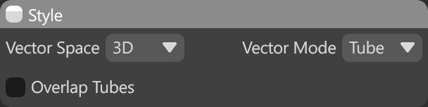
Style #
The Style settings define how a Vector layer is created and behaves, controlling whether vectors are drawn in 2D or 3D, the types of shapes they produce, and how overlapping vector shapes are handled.
| Setting | Description |
|---|---|
| Vector Space | Determines the coordinate space vector shapes are drawn and projected from. Decal Mode – Projection mode introduced in Toolbag 5.02, enabling you to create shapes on a virtual plane that are projected onto the mesh. It’s useful to design logos and complex mechanical parts. 3D – Projection mode that lets you draw and edit vector shapes directly on the mesh in 3D space. It’s useful to add path-based details such as seams, tubes, wires, etc. |
| Vector Mode | Select fill mode of vector shapes. Tube – Creates path-based vector shapes with width. This mode is useful for elements such as stitches, cables, panel lines, and other path-following line-based details. Solid – Creates filled vector shapes with an enclosed area. This mode is useful for panels, portholes, vents, and other surface details that require a solid shape rather than a line. Brush – Creates free-drawn vector shapes using brush strokes. This mode is useful for adding organic or irregular details, such as wear patterns, grunge, and surface variation. It can also be used to place repeated surface details such as bolts and nuts. You can learn more about Brush settings here [link]. Note: To create a custom brush, make sure the Fit to Brush projection method is selected. |
| Overlap Tubes | Determines whether tube shapes are allowed to overlap each other. Note: This setting is available only in Tube and Solid modes. |
| Splots at Points | Determines whether the brush splots is drawn only at vector points. This is useful for creating controlled paths of repeated elements, such as bolts or rivets. Note: This setting is available only in Brush mode. |
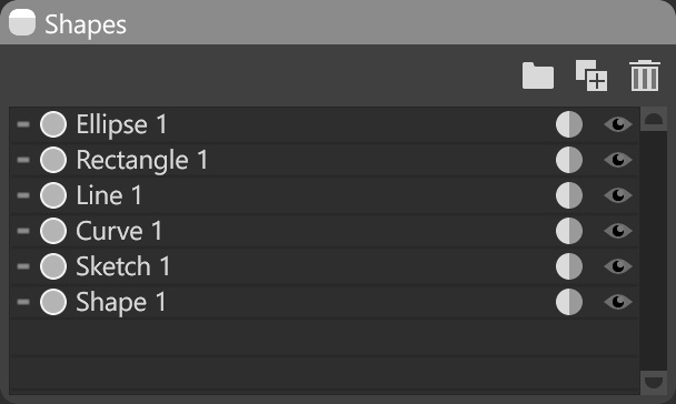
Shapes #
The Shapes section displays a list of all vector shapes created in the Vector layer. It allows you to select and edit shapes individually or as a group.
| Setting | Description |
|---|---|
| Group | Group selected items. |
| Duplicate | Duplicate selected items. |
| Delete | Delete selected items. |
| Shapes List | List of all vector shapes in this layer. |
Profile #
The Profile section defines a displacement contour (profile) to extrude along the edges of a vector shape.
| Setting | Description |
|---|---|
| Presets | List of profile presets. |
| Edit | Open the profile editor to create a custom displacement contour. |
| Delete Preset | Remove selected profile from the presets list. |
| Save Preset | Save the current profile as a preset. |
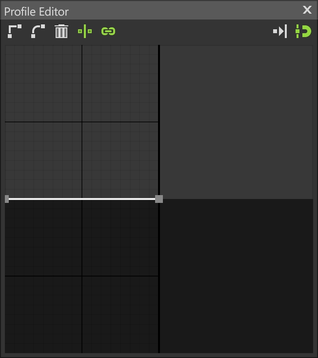
Profile Editor
| Setting | Description |
|---|---|
| Sharp Point | Sharpens the selected point. |
| Smooth Point | Smooths the selected point. |
| Delete | Deletes the selected point. |
| Mirror Handles | Mirrors the handles for the selected point. |
| Link | Links the length of the handles for the selected point. |
| Overlapping | Prevents moving points to overlapping positions. |
| Mirror Curve | Toggles horizontal mirroring for the whole profile curve. |
| Snapping | When enabled, bezier vertices and tangent handles will snap to a visible grid. Resize the Profile Editor window for a more refined grid. |
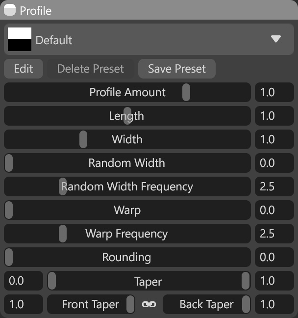
Profile Settings
| Setting | Description |
|---|---|
| Profile Amount | Sets the height scale of the profile in bump and displacement maps. |
| Length | Controls tiling of shape-projected materials and alpha masks along the shape edges. |
| Width | Sets the profile width along the shape edges. |
| Random Width | Adds random variation to the profile width. |
| Random Width Frequency | Sets the frequency of random variation in the profile width. |
| Warp | Adds random side-to-side wiggle to shape edges. |
| Warp Frequency | Sets the frequency of side-to-side wiggle on shape edges. |
| Rounding | Controls rounded caps on the start and end of shape edges. Note: This setting is available only in Tube mode. |
| Taper | Controls narrowing of contour width at the start and end of shape edges. Note: This setting is available only in Tube mode. |
| Front Taper | Controls narrowing of contour width at the start of shape edges. Note: This setting is available only in Tube mode. |
| Back Taper | Controls narrowing of contour width at the end of shape edges. Note: This setting is available only in Tube mode. |
Symmetry #
The Symmetry section controls how vector shapes are mirrored during creation and editing. It allows the use of standard (axis-based) or radial symmetry, making it easier to create repeating details while editing a single shape. You can learn more in this section [link].
Active Maps #
The Active Maps section specifies which texture maps are modified by the Vector layer. Only selected maps will affect the vector-generated details.
Material Projection #
The Material Projection section controls how vector details are applied to the surface, depending on the Projection Method. It adjusts how the vector shapes are mapped, ensuring proper alignment and positioning of the vector details across the surface.
In addition to the standard projection modes (UV, Tri-Planar, and Planar), there are projection modes specifically designed for Vector Layers: Fit to Spline, Fit to Brush, and Tile Strip.
- Fit to Spline – Fits a vector shape along the entire length of a spline, stretching it to match the spline path. This Projection Method is available in Tube Vector Mode.
- Fit to Brush – Fits a vector shape to individual brush strokes or points, allowing controlled placement of repeated elements along a path. This Projection Method is available in Brush Vector Mode.
- Tile Strip – Applies a modular strip made of tiled segments along a spline, repeating elements without stretching to maintain consistent detail size. This Projection Method is available in Tube Vector Mode. You can learn more about Tile Strips here.
Note: The Projection Method’s availability depends on the selected Vector Mode.
Material Properties #
The Material Properties section controls how the vector details impact the material. It lets you adjust how the vector shapes affect different material settings, such as color, roughness, and other surface properties, to match the desired look.
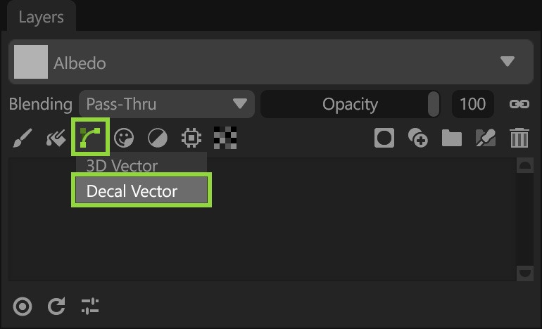
Decal Vector #
Decal Vector layers, introduced in Toolbag 5.02, use a Decal projection mode, enabling you to create shapes on a virtual plane with grid snapping, which are then projected onto the mesh. Working on the grid makes it easy to create precise shapes and perform Boolean operations for complex mechanical designs. This mode is especially useful for creating elements that would otherwise be difficult to model and align with the surface of your mesh, such as panels and cutouts on curved parts. Since the shapes live on the grid and are not aligned with your 3D mesh, moving and editing them is more predictable, allowing you to design in isolation and then position the element without altering the shape of the vectors.
Add a Decal Vector layer using the toolbar in the Layers window.
Note: Some settings in the Decal Vector layer differ from the 3D Vector layer settings. And unlike 3D mode, Decal vectors can also be projected across multiple meshes.
Editing the placement of a Decal Vector is easy with the viewport Decal Tool, which lets you click and drag along the surface of the mesh to reposition the element. You can also use the transform controls to adjust the size, rotation, projection distance, and falloff.
Toolbar #
The toolbar provides quick access to tools for creating, selecting, and editing vector shapes within a Vector layer.
| Setting | Description |
|---|---|
| Decal Tool | Activates the decal manipulator for positioning and adjusting a Decal layer in the scene. |
| Decal Transform | Activates the decal manipulator to position and adjust a Decal layer in the scene. |
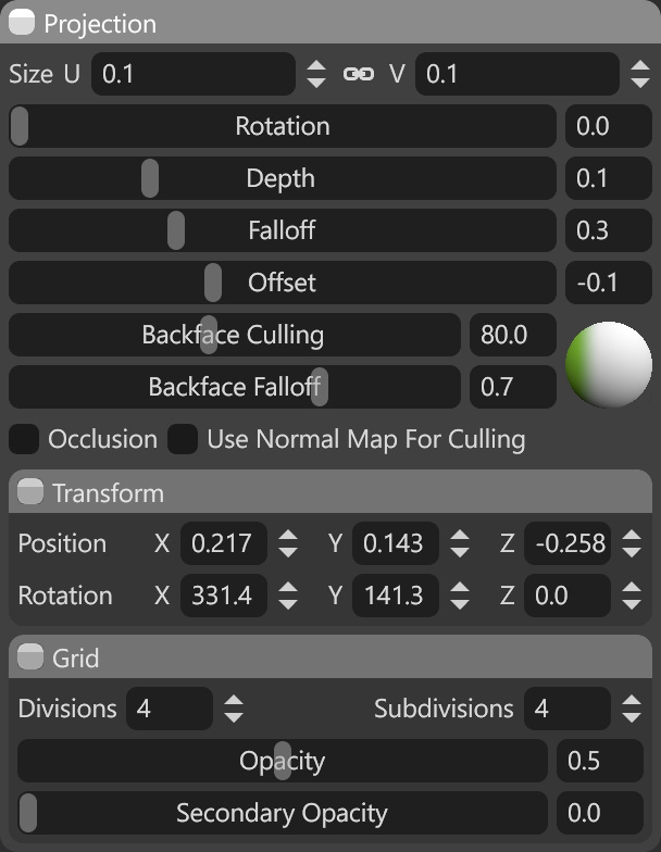
Projection #
The Projection section defines how a Decal layer is projected onto the mesh surface. It controls the overall behavior of the projection, including its spatial alignment, depth interaction with the surface, and how the decal blends and fades across geometry.
Projection Settings
| Setting | Description |
|---|---|
| Size U | Sets the size of the projected plane on the horizontal axis as a ratio of the texture project’s mesh(es). |
| Size V | Sets the size of the projected plane on the vertical axis as a ratio of the texture project’s mesh(es). |
| Rotation | Sets the angle of the material properties. |
| Depth | Sets the maximum distance beneath the surface at which the projection will be drawn. Smoothly fades from falloff value. |
| Falloff | Sets the distance beneath the surface at which the projection will start fading. |
| Offset | Sets the maximum distance above the surface at which the projection will be drawn. No falloff is applied. |
| Backface Culling | Sets the maximum angle the tool will paint on relative to the center point of the brush. |
| Backface Falloff | Sets how gradually the culling function fades to the maximum value. |
| Occlusion | Sets whether the occlusion map influences the culling function. When on, the surface details in the occlusion map will be used for culling. |
| Use Normal Map for Culling |
Transform
| Setting | Description |
|---|---|
| Transform Position | Sets the X, Y, and Z axis 3D space position for the projection in relation to the texture project’s mesh(es). |
| Transform Rotation | Sets the X, Y, and Z axis 3D space rotation for the projection in relation to the texture project’s mesh(es). |
Grid
| Setting | Description |
|---|---|
| Divisions | Sets the number of visible divisions in the decal grid. |
| Subdivisions | Sets the number of subdivisions per division in the decal grid. |
| Opacity | Adjusts the opacity of the main grid area. |
| Secondary Opacity | Adjusts the opacity of the outer grid area. |